Test Light vs Multimeter: How the Wrong Tool Can Fry Your Car’s ECU

Your grandfather’s test light found a blown fuse in about four seconds. It also would have cost you a $900 engine control module if he had touched it to the wrong pin on a 2021 Silverado.
That is the whole problem in one sentence. The tool did not change. The car did.
Test Light vs Multimeter: The Short Answer
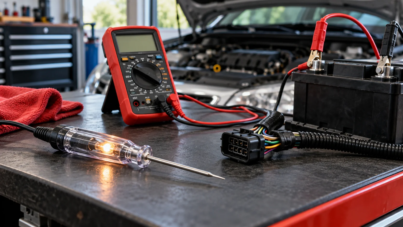
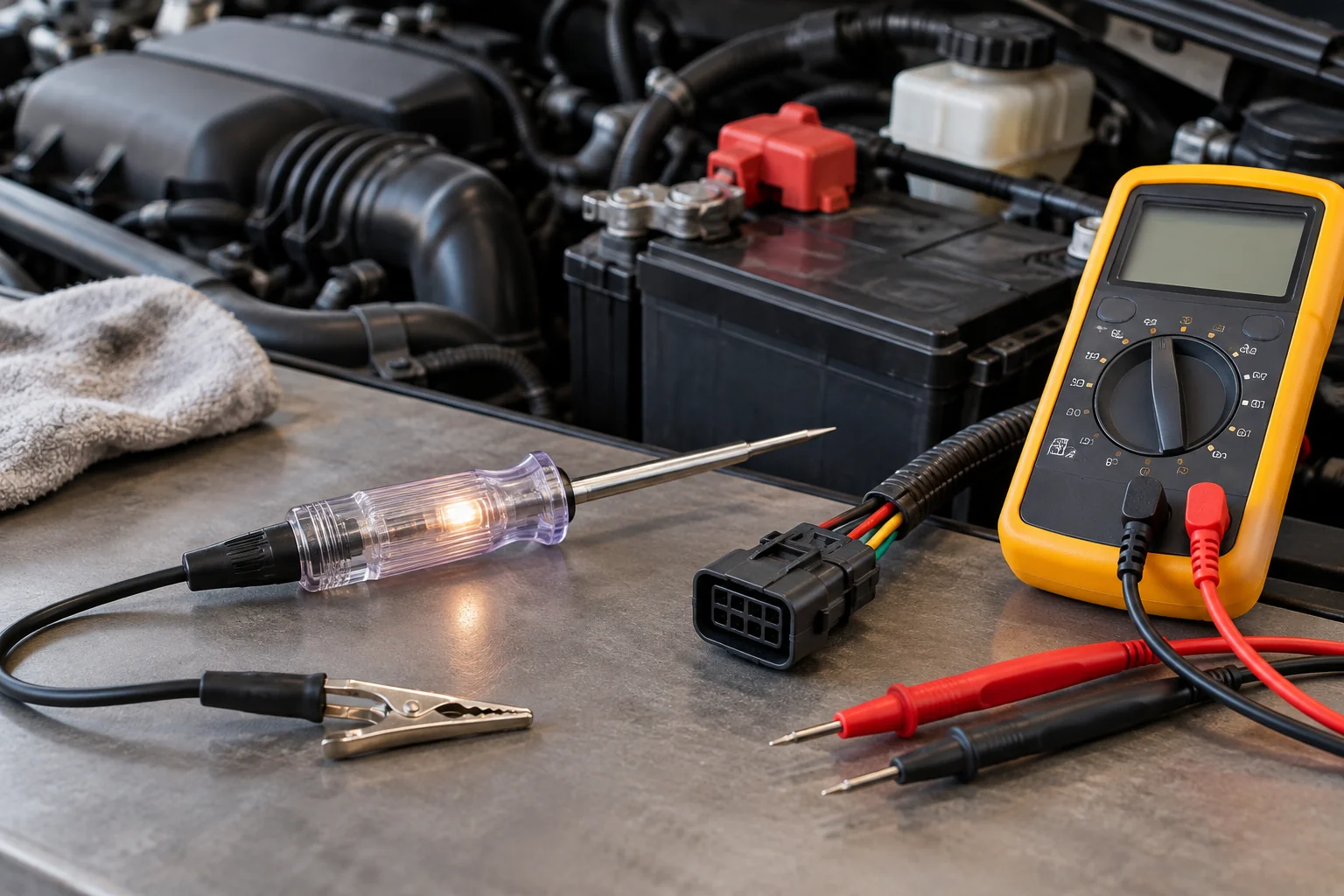
Use a test light on high current circuits only, like headlight feeds, horn wiring, and fuse box hot sides. Use a 10 MΩ digital multimeter on anything connected to a computer, sensor, or control module. A test light draws roughly 200,000 times more current than a DMM, and that current has to come from somewhere.
Choose a test light when:
- You are chasing power on a lighting, horn, or starter trigger circuit
- You need a fast yes or no on a fuse or a battery feed
- You want to see a circuit under actual load, not just a floating reading
Choose a digital multimeter when:
- Anything you are probing runs back to an ECU, BCM, TCM, or ABS module
- You are testing a 5V reference, a sensor signal, or a ground path
- You need a number, not a glow
At-a-Glance Comparison Table
| Criteria | Incandescent Test Light | Analog Voltmeter | 10 MΩ Digital Multimeter |
|---|---|---|---|
| Internal resistance | Roughly 50 Ω | Around 100 kΩ | 10,000,000 Ω |
| Current pulled from circuit at 12V | ~250 mA | ~120 µA | 1.2 µA |
| Safe on ECU driver pins | No | No | Yes |
| Reading accuracy on high resistance circuits | None (go / no-go only) | Poor, reads low | Within 0.5% |
| Shows a weak circuit under load | Yes | Partially | No, this is its blind spot |
| Cost of a mistake | Fried module | False diagnosis | Wasted time |
The last row is the one that matters. A wrong test light reading costs money. A wrong multimeter reading costs an afternoon.
Why Modern Cars Punish Old Tools
A modern car is a network of small computers running on 5V reference signals, not a wiring loom running on 12V. The transistors inside an ECU are microscopic and rated in milliamps. Old test tools were built for headlight-sized current, so pushing that much through a control pin destroys silicon that was never designed to carry it.
Think about what an ECU actually does when it turns on a fuel injector. It does not switch a big mechanical relay contact. It switches a solid-state driver, a transistor etched onto a die, sized for exactly the current that injector needs and not one milliamp more.
Now consider a 5V reference circuit feeding a throttle position sensor. The ECU generates that 5V internally from a regulator. The entire circuit might carry a few milliamps on a busy day.
Touch a test light to it.
The lamp does not care about design intent. It wants a quarter of an amp to heat its filament, and it will pull that current from whatever is on the other end of the probe. In this case, the other end is a regulator on a circuit board buried behind the glovebox. Something has to give, and it is never the test light.
Related reading: if you have already had a module go strange on you, see our guide on how to reset a car computer without disconnecting the battery before you assume the worst.
Why Incandescent Test Lights Damage ECUs
An incandescent test light works by completing a circuit through its own filament, which needs high current to glow. Its internal resistance sits around 50 ohms, so it pulls roughly 250 milliamps at 12 volts. When you back-probe an ECU output pin, the module’s internal driver has to supply all of that current, and the transistor burns out.
Here is the part most DIY guides skip: the bulb is not a passive indicator. It is a load. The only reason it lights up is that current is physically flowing through it, and that current has to be sourced by the circuit you are testing.
On a headlight feed, this is fine. The circuit was built to run a 55 watt bulb. A test light is a rounding error.
On a computer-controlled ground circuit, it is not fine. Many modern ECUs switch the ground side of a component rather than the power side. Back-probe that switched ground with a test light while the module is commanding the circuit off, and you have just handed the driver transistor a quarter amp it cannot dump anywhere. The chip fails, sometimes instantly, sometimes three weeks later when you have already sold the car.
Nobody hears a pop. There is no smoke. The circuit just stops working, and now you are diagnosing a fault you created.
The Analog Voltmeter Problem Nobody Warns You About
Analog sweep-needle voltmeters typically carry an internal resistance near 100,000 ohms, which is low enough to load a circuit heavily. At best the needle shows a lower voltage than the circuit actually has, sending you chasing a voltage drop that does not exist. At worst the current draw kills a solid-state chip, the same way a test light does.
The needle is honest about what it is measuring. It is just measuring the wrong thing, because the act of connecting it changed the circuit.
Run the numbers on a 100 kΩ sensor divider and the scale of the problem shows up fast. The true voltage at the midpoint is 6V. Put a 100 kΩ analog meter across it and the parallel combination collapses to 50 kΩ. The meter now reads 4.0 volts.
You are looking at a 33% error and a perfectly functional circuit that appears to have a serious voltage drop. So you replace a sensor. Then a harness. Then the module. The fault was in your hand the entire time.
Old meters have a place. That place is a battery terminal, an alternator output, or anything else that can shrug off a milliamp of parasitic draw.
Why 10 MΩ Input Impedance Is the Number That Matters
Buy a meter with at least 10 megohms of input impedance and nothing else on the spec sheet matters much for automotive work. At 12 volts, a 10 MΩ meter draws 1.2 microamps, which is small enough that the circuit does not notice it is being measured. Anything below 1 MΩ will distort readings on high resistance circuits and can stress low current control lines.
Input impedance is the resistance the meter presents to whatever it touches. Higher is better, always, with no tradeoff you will ever feel in a garage.
The number is printed on the spec sheet, usually as “input impedance: 10 MΩ” or “10 MΩ, DC.” If a meter does not list it, that silence is your answer. Cheap parts-store meters often sit at 1 MΩ or lower, and the ones that do not publish the figure are rarely publishing it out of modesty.
One more thing worth checking before you buy: auto-ranging. Manual ranging on a meter you use twice a year means fumbling with a dial while holding two probes and a flashlight. Not a safety issue, just an annoyance that will make you stop using the meter.
If you are still building out your electrical kit, our tool bag roundup for maintenance techs covers what to carry alongside the meter.
The Loading Effect, Proven With Simple Math
Every meter changes the circuit it measures by adding its own resistance in parallel. A 10 MΩ meter introduces about 0.5% error on a 100 kΩ circuit. A 1 MΩ meter introduces around 5% on the same circuit. That gap is the difference between a reading you can act on and a reading that invents a fault.
Set up the simplest possible test case. Two 100 kΩ resistors in series across a 12V supply. The true voltage at the midpoint is exactly 6V.
With a cheap 1 MΩ meter:
The meter’s 1 MΩ sits in parallel with the lower 100 kΩ resistor. Combined, that is about 91 kΩ. Total circuit resistance becomes 191 kΩ instead of 200 kΩ, so the meter displays 5.71 V. Your error is roughly 5%, and every bit of it was created by the tool.
With a professional 10 MΩ meter:
The parallel combination lands at 99 kΩ. Total resistance is 199 kΩ, and the display reads 5.97 V. Error drops to 0.5%, which is inside the tolerance of the resistors themselves.
With a 100 kΩ analog meter:
Parallel combination drops to 50 kΩ. The needle reads 4.0 V. Error is 33%.
The circuit never changed. The tool did.
This is why two people can probe the same wire, get different numbers, and both be reading their meters correctly.
The DMM Trap: Why a Perfect 12.6V Reading Can Be a Lie
A 10 MΩ multimeter is so gentle on a circuit that it will happily read 12.6V through a wire too corroded to run a fuel pump. At 1.2 microamps, even several thousand ohms of corrosion produces no measurable voltage drop. The display looks perfect. Then you turn the component on and the voltage falls to nothing.
Ohm’s law explains the whole trick. Voltage drop equals current times resistance. If current is 1.2 microamps, then even 5,000 ohms of green crusty corrosion produces a drop of 0.006 volts. Your meter cannot see that. Nothing can.
Now plug the component back in. The fuel pump wants 8 amps. Push 8 amps through that same 5,000 ohms and the math demands 40,000 volts, which the battery obviously cannot supply, so the circuit simply collapses. Voltage at the pump goes to near zero. The pump does not run.
This is the single most common false negative in DIY automotive electrical work. The wire tests good and is not good. The meter is not broken and you are not incompetent. You measured off-load when the fault only appears on-load.
Symptoms that look like this: a starter that clicks but does not crank, a blower that works on high only, an alternator that charges at idle but not under load. Our writeup on what causes a car starter to fail walks through the load-side version of this exact problem, and why a weak battery makes an engine run rough covers the same trap on the charging side.
How to Load-Test a Circuit Without Killing the ECU
Connect a test lamp in parallel with your multimeter to force current through the circuit while you watch the voltage. If the reading holds near 12.6V under that load, the wire is sound. If it collapses, you found your corrosion. Do this only on circuits that can safely carry the lamp’s current draw.
The procedure is simple:
- Probe the circuit with your DMM as usual. Note the off-load reading.
- Clip a test lamp across the same two points, so the lamp and meter are in parallel.
- Watch the meter as the lamp lights.
- A healthy wire holds voltage. A corroded wire drops several volts instantly.
Now the warning, and it is the important half. Never do this on an ECU switching circuit. You are deliberately introducing the exact current that damages module drivers, so the technique belongs on power feeds and grounds that were built to carry real amperage, not on control lines.
If you are unsure whether a wire runs to a module, assume it does. The cost of being wrong in that direction is a wasted five minutes. The cost of being wrong in the other direction is a replacement module and a programming appointment.
A safer alternative on lower current circuits: a purpose-built loaded test lead, or a headlight bulb wired to two leads, which lets you pick a known load instead of guessing.
Ghost Voltages and the Shake Test
Shake your test leads while watching the display. A ghost voltage jumps around erratically because it is induced noise picked up by open leads acting as an antenna. A real voltage, including a bad ground reading, stays rock steady no matter how much you move the leads. This test takes two seconds and saves whole afternoons.
High impedance meters are wonderfully sensitive, which is also their weakness. Run a test lead alongside a live harness and the lead will capacitively pick up enough signal to display a few volts on an open circuit. It looks like a real reading. It is electrical noise.
Where this bites people: ground testing. You put your black lead on the battery negative, your red lead on a chassis ground point, and the meter shows 0.4V. Bad ground, right?
Shake the leads.
If the number dances between 0.1 and 0.9, it is a ghost. If it sits at 0.4 and refuses to move, you have a genuine voltage drop across a ground connection, and that connection needs cleaning.
Back-Probing Without Ruining the Connector
Never force multimeter probes into the front face of a connector. Standard probes are thicker than the terminals they are entering, so they spread the female contact permanently and create an intermittent open circuit that will haunt the car for years. Back-probe instead, sliding a T-pin or a sewing pin down the back of the terminal alongside the wire.
The failure mode here is cruel. You spread a terminal today, the car works fine on the drive home, and six months later the owner has an intermittent misfire that nobody can reproduce. The connector looks perfect. The terminal is just slightly loose.
What to use instead:
- T-pins from a fabric store, cheap and easy to hold
- Sewing dress pins, thin enough for almost any terminal
- Purpose-built back-probe kits, worth it if you do this weekly
- Piercing probes, acceptable on older vehicles, though the pierced insulation invites corrosion later, so seal it
Slide the pin in from the wire side of the connector until it contacts the metal terminal, then clip your meter lead to the exposed end. The connector stays sealed, the terminal stays tight, and the car goes back together the way it came apart.
Which Tool for Which Job
You are chasing a dead headlight. Test light. The circuit carries several amps and a fast go / no-go answer beats a precise number.
You are diagnosing a check engine light for a throttle position sensor. Multimeter, 10 MΩ, back-probed with a T-pin. That sensor runs on a 5V reference. A test light near it is a repair bill.
You are checking whether a fuse is live. Test light on the fuse box hot side is faster and reads under a small load.
Your starter clicks but will not crank. Multimeter first for the off-load reading, then a loaded test on the battery cable and ground strap. Off-load readings lie on high current circuits. Our guide on what a bad starter sounds like helps narrow this down before you pull anything apart.
You are anywhere near an airbag, CAN bus, or ABS module. Multimeter only, and read the service information first. Some of these circuits should not be probed at all with power applied.
Frequently Asked Questions
Can a test light damage a car computer?
Yes. An incandescent test light pulls roughly a quarter amp through whatever it touches. Back-probe an ECU driver pin with one and that current flows through the chip, which can burn the output transistor instantly and permanently.
Is an LED test light safe on ECU circuits?
Usually, yes. A quality LED test light draws a few milliamps instead of hundreds, so it lights up without loading the circuit hard. Check the spec sheet though, since some cheap LED lights still use a resistor sized for heavy current.
What input impedance do I need on an automotive multimeter?
Ten megohms minimum. That is the accepted floor for automotive electronics work. A 10 MΩ meter draws about 1.2 microamps at 12 volts, small enough that it reads a five volt reference sensor circuit without shifting the voltage.
Why does my multimeter read 12V when the circuit is dead?
Because your meter barely loads the circuit. At 1.2 microamps, even a badly corroded wire with several thousand ohms of resistance drops almost no voltage. Turn the component on and that same wire collapses to near zero volts.
What is ghost voltage on a multimeter?
Ghost voltage is a false reading picked up by open test leads acting as an antenna near live wiring. Shake the leads while watching the display. A ghost reading jumps around wildly. A real ground fault holds steady.
Can I still use a test light on a modern car at all?
Yes, on high current circuits only. Headlight feeds, starter triggers, fuse box hot sides, and horn wiring all tolerate a test light fine. Keep it away from sensor wiring, ECU pins, CAN bus lines, and airbag circuits.
The Call
Buy the 10 MΩ multimeter. Keep the test light.
Both belong in the drawer, and the skill is knowing which one to reach for. The meter tells you what the voltage is. The test light tells you whether the circuit can actually do work. Neither answers the other’s question, and a diagnosis built on only one of them is half a diagnosis.
The rule that keeps modules alive: if the wire goes to a computer, the meter comes out. If you are not sure whether it goes to a computer, the meter still comes out.