Demystifying the CAN BUS: How Cars Got Rid of Miles of Heavy Wiring

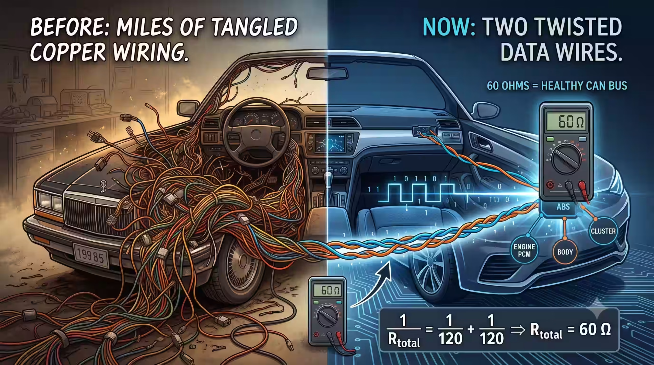
A 1985 luxury sedan carried more than half a mile of copper wiring and over 500 individual terminals, all of it stuffed behind the dash and under the carpet so a switch could talk to a motor. A modern car does more, with more features, over two twisted wires.
That’s the CAN bus system, and once you understand what those two wires are doing electrically, network diagnostics stops being guesswork and becomes a multimeter reading.
Why carmakers replaced point-to-point wiring with multiplexing
Point-to-point wiring gives every switch its own dedicated copper loop running to its actuator. Multiplexing combines many independent messages onto a single shared path, so one pair of wires carries data for dozens of modules instead of one circuit carrying one signal.
Picture what happens to a wiring harness when you add power windows, then climate control, then ABS, then a body control module, then infotainment. Each new feature under the old approach means new wire from the switch, through the firewall, to the device, plus grounds, plus fuses. The harness gains weight, the loom gains diameter, and every added splice adds a failure point.
By the mid-1980s that curve stopped working. The wiring bundle passing through the driver’s door on a loaded car was getting thick enough to interfere with the hinge.
Multiplexing solved it by changing what the wires carry. Instead of current going to a device, the wires carry data about what the device should do. Your window switch no longer feeds the window motor. It tells the door module “switch closed,” the door module broadcasts that on the network, and the module physically next to the motor handles the current. The heavy wire got short. The long wire got thin.
Think of it like a bus route. Under point-to-point, every passenger needs a private car and a private lane. Under multiplexing, everyone rides the same vehicle and gets off at their own stop.
How the CAN bus system actually moves messages
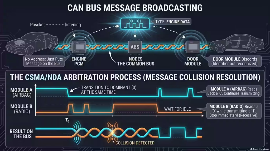
The CAN bus system broadcasts every message to every module at once, with no destination address and no master controller. Each module, called a node, listens to everything on the bus and decides on its own whether to act on a message or ignore it based on the message’s identifier.
Robert Bosch GmbH developed CAN in 1983 and released it publicly in 1986. The design choice that makes it work is the absence of routing. There’s no server, no addressing scheme like an office network uses, and no single module whose failure takes down everything else.
When the engine controller broadcasts coolant temperature, it doesn’t send that reading to the instrument cluster. It just puts the message on the bus. The cluster sees the identifier, recognizes it as something it cares about, and uses it. The transmission controller also sees it, also cares, and uses it for shift scheduling. The door module sees it and discards it. One transmission, several consumers, zero addressing overhead.
Message arbitration: why zero always wins
Two modules can start transmitting at the same instant, and CAN resolves that collision without either message being destroyed. The protocol is called CSMA/NDA, or Carrier Sense Multiple Access with Non-Destructive Arbitration.
As each module transmits its identifier bit by bit, it reads back what’s actually on the bus. In CAN’s electrical logic, logic 0 is dominant and logic 1 is recessive. If a module transmits a 1 but reads a 0 on the bus, it knows another module is sending a higher-priority message right now. It stops transmitting immediately, without corrupting the message in progress, and waits.
Lower binary ID equals higher priority. Airbag deployment and ABS intervention carry very low identifiers. Your seat heater does not.
Network classes and speed tiers
Not everything on a car needs 1 Mbit/s. Automotive networks split into classes by speed and criticality:
| Class | Speed | Typical use |
|---|---|---|
| Class A | Below 10 kbps | Convenience and entertainment functions |
| Class B | 10 to 125 kbps | Module-to-module data sharing such as temperatures |
| Class C | 125 kbps to 1 Mbps | Safety-critical systems: engine PCM, ABS, airbags |
High-speed CAN runs up to 1 Mbit/s over a maximum bus length of 40 meters. That length limit isn’t arbitrary. It comes from signal propagation time versus bit duration, which is the same physics that makes terminating resistors necessary.
Why CAN wires are twisted together
The two CAN wires are twisted to cancel electromagnetic interference. Any current flowing through a straight wire generates a magnetic field, and any external field induces voltage back into nearby wires. Twisting the pair means an interference spike hits both wires almost identically, and because the receiver reads the difference between them, the noise subtracts itself out.
This is differential signaling, and it’s the reason a data network survives sitting six inches from an ignition coil.
The two lines are CAN High (CAN_H) and CAN Low (CAN_L). Neither one carries the message on its own. The message lives in the voltage difference between them.
| Bus state | CAN_H | CAN_L | Differential voltage |
|---|---|---|---|
| Recessive (logic 1, idle) | 2.5 V | 2.5 V | 0 V |
| Dominant (logic 0, active) | 3.5 V | 1.5 V | 2.0 V |
Follow what happens during a noise event. An alternator diode spike induces, say, 4 volts into the harness. On a single-ended signal wire, that 4 volts would ride straight into the receiver and corrupt the bit. On a twisted pair, CAN_H goes from 3.5 V to 7.5 V and CAN_L goes from 1.5 V to 5.5 V. The difference between them is still exactly 2.0 volts. The receiver reads a clean dominant bit and never knows anything happened.
Untwist a section of that pair during a repair and you break the geometry that makes the cancellation work. This is why splicing into CAN lines with a long unpaired pigtail causes intermittent faults that show up only when the blower motor or the fuel pump kicks on.
Why the CAN bus needs two 120-ohm terminating resistors
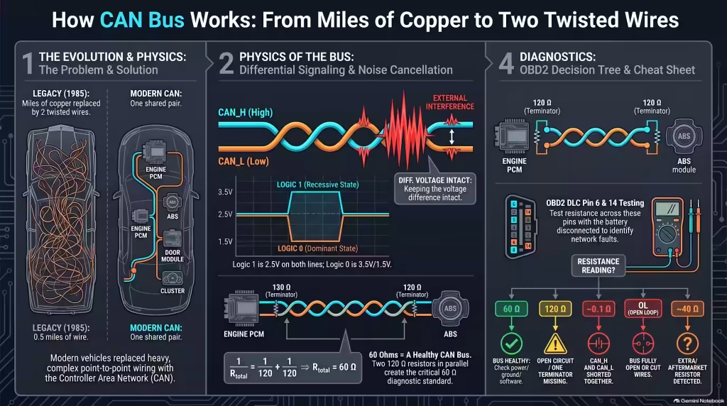
A high-speed digital pulse reaching the open end of a wire reflects backward like an echo in a hallway, and that reflection collides with incoming data and corrupts it. A 120-ohm resistor at each end of the bus matches the characteristic impedance of the twisted pair, absorbing the pulse instead of bouncing it back.
Two resistors, one at each physical end, sitting electrically in parallel across the same two wires. Run the parallel resistance formula:
1/R_total = 1/R1 + 1/R2
1/R_total = 1/120 + 1/120
1/R_total = 2/120
R_total = 60 Ω
Sixty ohms. That single number is the most useful thing you can know about diagnosing a CAN bus system, because it turns an invisible digital network into something a twelve-dollar multimeter can evaluate.
The resistors aren’t standalone components you can point at. They live inside two modules at opposite ends of the bus, typically the engine controller and one other node such as the ABS module or the instrument cluster. Unplug one of those modules and you’ve physically removed a terminator from the circuit.
How to test a CAN bus with a multimeter at the DLC
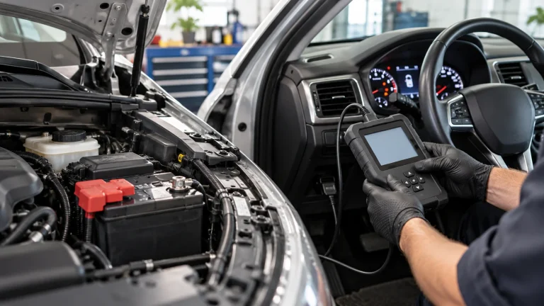
Measure resistance between pin 6 and pin 14 of the 16-pin OBD2 connector with the battery disconnected. A healthy high-speed CAN bus reads 60 ohms. Anything else tells you specifically what kind of fault you have before you pull a single panel.
Step 1: Check battery state of charge
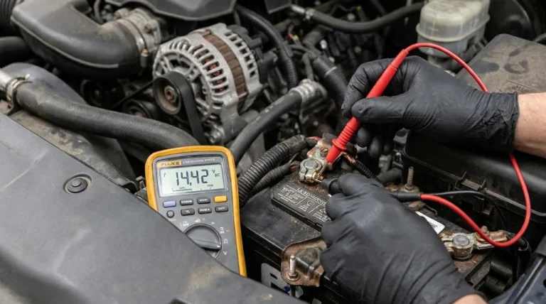
The battery must read at least 12.45 volts, which corresponds to 75% state of charge. Below that, modules brown out and produce communication codes that have nothing to do with the network wiring. Chasing a U-code on a weak battery wastes hours. If the vehicle has a history of stalling or dying in traffic, sort why the battery dies while driving first, and understand that a weak battery can make an engine run rough in ways that mimic sensor faults.
Step 2: Disconnect the negative battery terminal
Resistance measurement works by pushing a small known current through a circuit and measuring the voltage drop. Any live voltage on the bus fights that current and gives you a garbage number. Pull the negative cable and wait two minutes for capacitors to drain.
Be aware this clears adaptive memory on most vehicles. If you’d rather avoid that, there are ways to reset a car computer without disconnecting the battery, though for a resistance test the disconnect is non-negotiable.
Step 3: Measure across pins 6 and 14
Set the meter to ohms. Backprobe pin 6 (CAN_H) and pin 14 (CAN_L) on the DLC. Here’s what each reading means:
| Reading | Diagnosis |
|---|---|
| 60 Ω | Both terminating resistors present, bus wiring physically healthy. Your fault is elsewhere: software, power, or grounds. |
| 120 Ω | One end of the network is open. A broken wire, an unseated connector, or a disconnected module containing a terminator. |
| ~0.1 Ω | CAN_H and CAN_L are shorted together, usually a chafed harness against a bracket or a crushed loom. |
| OL (open loop) | Both lines are cut, or the bus is completely open. Check for a disconnected harness section. |
| ~40 Ω | A third terminating resistor has been added somewhere, often by an aftermarket accessory installer. |
That 120-ohm case is the most common and the most actionable. Half the network is answering, half isn’t. Start unplugging modules one at a time and re-measuring. When the reading jumps from 120 to OL, you just unplugged the remaining terminator, which tells you which end of the bus is still intact.
Step 4: Verify power and grounds at the DLC
Reconnect the battery. Check for battery voltage at pin 16. Check pin 4 (chassis ground) and pin 5 (signal ground) for continuity to a clean chassis point.
Ground quality matters more than most people expect. A module ground with 0.2 volts of drop across it generates communication errors that scatter across unrelated systems, because the module’s reference for “2.5 volts” is no longer the same reference every other module is using. Stability control faults in particular tend to trace back to grounds, and fixing a VSA system fault often starts with a connector cleanup rather than a module replacement.
Step 5: Interrogate every aftermarket accessory
Non-factory equipment spliced into network lines is the leading cause of modern communication faults. Remote starters, aftermarket stereos, GPS trackers, dashcams hardwired to the OBD port, and trailer brake controllers all sit at the top of the suspect list.
The installer who tapped CAN_H for a “12 volt switched” feed didn’t know what he was looking at. It happens constantly. Anything spliced into the ignition circuit deserves the same scrutiny, which is worth reading up on if someone has been working around the ignition switch on the vehicle.
Disconnect every add-on, clear codes, and re-test. If the network comes back, you’ve found it.
What a healthy CAN bus looks like on a scope
Resistance testing proves the wiring is intact. It says nothing about whether modules are actually talking. For that you need a scope, and what you’re looking for is a clean square wave with sharp transitions between 2.5 V and 3.5 V on CAN_H, mirrored by 2.5 V down to 1.5 V on CAN_L.
Rounded edges mean capacitance somewhere it shouldn’t be, usually water in a connector. Ringing after each transition means a termination problem even when the 60-ohm reading looked fine, which happens when a resistor drifts high with age. Flat lines at 2.5 volts with no activity mean the physical layer is fine but nothing is transmitting, which points at power or at a module holding the bus in bus-off state.
Frequently asked questions
What should a healthy CAN bus read on a multimeter?
Exactly 60 ohms between pin 6 and pin 14 of the DLC, measured with the battery disconnected. That number comes from two 120 ohm terminating resistors sitting in parallel at opposite ends of the high speed bus.
Can you drive with a U code stored?
Sometimes, but treat it as a warning. U codes mean modules stopped talking, so features like ABS, stability control, and power steering assist can drop out without notice. Get the network checked before the next long trip.
What usually causes CAN bus failure?
Wiring damage and bad grounds cause most of it. Spliced aftermarket accessories, rodent chewed harnesses, corroded connectors, and a module ground dropping 0.2 volts will all scramble differential signals and throw communication codes across unrelated systems.
Where are CAN terminating resistors located?
Inside two modules at opposite ends of the high speed bus, usually the engine controller and one other node such as the ABS or instrument cluster. They are internal, so a disconnected module removes one resistor and doubles your reading.
What voltage should CAN high and CAN low read?
Both sit at 2.5 volts when the bus is idle. During active transmission CAN high rises to about 3.5 volts and CAN low drops to about 1.5 volts, giving a differential swing near 2.0 volts.
Why disconnect the battery before a resistance test?
Because a multimeter measures resistance by pushing its own small current through the circuit. Any voltage still on the bus fights that current and skews the reading, so a healthy 60 ohm network can look shorted or open.